 Rear upper arm assembly (multi-link configuration)后上臂总成(多连杆配置)
|

Removal procedure拆卸程序
|
1. Preparation1. 准备工作
1 Drive the vehicle into the lift position, activate the parking brake, and put the vehicle power supply in the "OFF" state.将车辆驶入举升机举升位置,启用驻车制 动,整车电源处于“OFF”状态。
2 Disconnect the negative terminal of the 12V battery.断开蓄电池负极。
3 Lift the vehicle.举升车辆。
|
|
2. Remove the left rear wheel assembly2. 拆卸左后车轮总成
|
|
3. Remove the right rear wheel assembly3. 拆卸右后车轮总成
|
|
4. Remove the left rear wheel fender assembly4. 拆卸左后轮挡泥板总成
|
|
5. Remove the right rear wheel fender assembly5. 拆卸右后轮挡泥板总成
|
|
6. Remove the rear floor guard body (multi-link configuration)6. 拆卸后地板后下护板本体(多连杆配置)
|
|
7. Remove the rear floor and front lower guard body (multi-link configuration)7. 拆卸后地板前下护板本体(多连杆配置)
|
|
8. Remove the rear floor panel bracket (multi-link configuration)8. 拆卸后地板底护板支架(多连杆配置)
|
|
9. Remove the rear sliding column assembly (multi-link configuration)9. 拆卸后滑柱总成(多连杆配置)
|
|
10. Disassemble the motor-integrated left rear caliper assembly10. 拆卸电机集成式左后卡钳总成
|
|
11. Disassemble the motor-integrated right rear caliper assembly11. 拆卸电机集成式右后卡钳总成
|
|
12. Remove the rear subframe assembly (multi-link configuration)12. 拆卸后副车架总成(多连杆配置)
|
|
13. Disassemble the rear upper arm assembly13. 拆卸后上臂总成
|
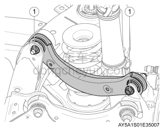 |
1 Remove the 2 fixing nuts and bolts ①, and remove the rear upper arm assembly.拆卸2颗固定螺母及螺栓①,取下后上臂总成。
|
Installation procedure安装程序
|
1. Install the rear upper arm assembly1. 安装后上臂总成
|
|
|
1 Place and adjust the rear upper arm assembly to the installation position, install 2 fixing bolts and nuts ① and tighten them.放置并调整后上臂总成到安装位置,安装2颗固定螺栓及螺母①并紧固。
|
|
2. Install the rear subframe assembly (multi-link configuration)2. 安装后副车架总成(多连杆配置)
|
|
3. Install the motor-integrated right rear caliper assembly3. 安装电机集成式右后卡钳总成
|
|
4. Install motor-integrated left rear caliper assembly4. 安装电机集成式左后卡钳总成
|
|
5. Install the rear sliding column assembly (multi-link configuration)5. 安装后滑柱总成(多连杆配置)
|
|
6. Install the rear floor panel bracket (multi-link configuration)6. 安装后地板底护板支架(多连杆配置)
|
|
7. Install the rear floor and front lower guard body (multi-link configuration)7. 安装后地板前下护板本体(多连杆配置)
|
|
8. Install the rear floor guard body (multi-link configuration)8. 安装后地板后下护板本体(多连杆配置)
|
|
9. Install the right rear wheel fender assembly9. 安装右后轮挡泥板总成
|
|
10. Install the left rear wheel fender assembly10. 安装左后轮挡泥板总成
|
|
11. Install the right rear wheel assembly11. 安装右后车轮总成
|
|
12. Install the left rear wheel assembly12. 安装左后车轮总成
|
|
13. Carry out four-wheel alignment13. 进行四轮定位
|
|
14. Land the vehicle, connect the negative terminal of the 12V battery, start the vehicle and drive away from the lift, conduct a road test and check14. 降落车辆,连接蓄电池负极,起动车辆并驶离举升机,路试检查
|