|
|
 Note:提示: |
|
♦
|
The disassembly and assembly procedures for the left and right front transverse stabilizer bar assemblies are basically the same. The following content takes the left side as an example.左、右前横向稳定杆拉杆总成的拆装程序基本相同,下述内容以左侧为例进行操作。 |
|
|
Removal procedure拆卸程序
|
|
1. Preparation1. 准备工作
1 Drive the vehicle into the lift position, activate the parking brake, and put the vehicle power supply in the "OFF" state.将车辆驶入举升机举升位置,启用驻车制动,整车电源处于“OFF”状态。
2 Lift the vehicle.举升车辆。
|
|
|
2. Remove the left front wheel assembly2. 拆卸左前车轮总成
|
|
|
3. Remove the front transverse stabilizer bar tie rod assembly3. 拆卸前横向稳定杆拉杆总成
|
|
|
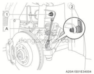
1 Remove the fixing nuts ① and ②, and remove the front transverse stabilizer rod assembly A.拆卸固定螺母①、②,取下前横向稳定杆拉杆总成A。
|
|
Recommended tools: 18mm socket, 18mm torx wrench推荐工具:18mm套筒、18mm梅花扳手 |
|
|
|
Note:提示: |
|
♦
|
During operation, if the ball head rotates with the nut, use a 6mm Allen wrench to secure it.操作时,如果球头随螺母一起转动,则使用6mm内六角扳手对其进行固定。 |
|
|
|
Installation procedure安装程序
|
|
1. Install the front transverse stabilizer rod assembly1. 安装前横向稳定杆拉杆总成
|
|
|
1 Place and adjust the front transverse stabilizer rod assembly A to the installation position, install and tighten the fixing nuts ① and ②.放置并调整前横向稳定杆拉杆总成A到安装位置,安装固定螺母①、②并紧固。
|
|
Recommended tools: 18mm socket, 18mm torx wrench推荐工具:18mm套筒、18mm梅花扳手 |
|
|
Torque requirement: 99-121N·m扭矩要求:99-121N•m |
|
|
|
Note:提示: |
|
♦
|
During operation, if the ball head rotates with the nut, use a 6mm Allen wrench to secure it.操作时,如果球头随螺母一起转动,则使用6mm内六角扳手对其进行固定。 |
|
|
|
|
|
2. Install the left front wheel assembly2. 安装左前车轮总成
|
|
|
3. Land the vehicle, start the vehicle and drive off the lift, conduct road test and check3. 降落车辆,起动车辆并驶离举升机,路试检查
|
 Front transverse stabilizer bar tie rod assembly前横向稳定杆拉杆总成